Processor Architecture
Programmer’s model, which describes the processor registers and provides information about programming the processor
Assembly instruction set used by the processor
- Actual processor features and behaviours are left as implementation defined. E.g. architecture does not define cycle timings for individual instructions or cache size
ARM-Cortex-M
registers are of 32-bit size
Byte: 8 bits; Halfword: 16 bits; Word: 32 bits
ARMv7 ARMs implement two instruction sets
- 32-bit ARM (A32) Instruction Set
- mixed 16-bit/32-bit Thumb-2 (T2 Thumb*) instruction set
Cortex-M3
Cortex-M3 can only execute the mixed 16/32 bits Thumb-2 (T2) instructions. T2 instructions set consists of
*     16-bit Thumb instructions (classic Thumb)
*
32-bit Thumb-2 instructions
32-bit T2 instruction is decoded:
*    the instruction length and functionality is determined by first halfword :31-16 .

*    the second halfword : 15-0 of the instruction is fetched from the instruction address plus two

Since Cortex-M3 can only execute T2 Thumb instruction set,  it can only operate in Thumb state   by setting the ‘T’ bit in the xPSR register to 1
Cortex-A which support both the A32 ARM state and T2 Thumb state .
Operating Modes
Handler mode:
a. program runs in foreground
b. entered as a result of an exception
c. always execute in Privileged access level, which allows access to all system resources
Thread mode:
a. program runs in background
b. can execute in either the Privileged access level or User access level
c. entered upon Reset, and can be re-entered as a result of an exception return
Cortex-M’s Stacks:
descending stack -> 就是新加入的item在低的地址, 每次递减 Stack Pointer
1.    Main Stack : only used in hander mode

2.    Processor Stack:  CONTROL register controls whether the processor uses the main stack or the process stack.
Cortex-M3 address space:
Different buses for fetching instructions and data:
*
Instruction ->AHB (Advanced Host Bus) bus 1-> Bus Matrix-> I-Code Bus->Code Memory Space
*    Data  -> AHB bus 2->          Bus Matrix->D-Code Bus->Code Memory Space


    Bus Matrix-> System Bus-> All memory
Memory areas that are not utilized in the implementation are usually indicated as RESERVED
address space supports the following primary regions:
*    Code (0.5 GB)

*    SRAM (0.5 GB)
*    Peripheral (0.5 GB)

*    External RAM region (1 GB)
*    External Device region (1 GB)
- System region, for Private Peripherals (0.5 GB)

Bit Banding:
maps a complete word (i.e. 32-bit size) of memory onto a single bit in the bit-band region-> 操作某个bit banding region的bit 位 通过 word-aligned address

Memory Protection Unit (MPU) : provide memory access control
Cortex-M Registers
- R0-R12: general purpose
- R0-R7: 16 or 32 bit T2 instruction
- R8-R12: only 32 bit T2 instruction
R13 (or call SP) : stack pointer
- Process Stack Pointer : SP_process (PSP): only be used when in Thread mode
*    Main Stack Pointer: SP_main (MSP)

    *        default stack pointer

    *        always used when in Handler mode
    *    can also be used when in Thread mode


    *     OS that needs to operate at privileged level
- R14 (LR) :link register
R15 (PC): program counter : points to the next instruction to be fetched
a. When an instruction reads the PC, the value read is the address of the instruction plus 4 bytes. Because of this, return from exception using the LR must adjust its value accordingly (more on this later).
bit register: xPSR
a. Applications Program Status Register (APSR ): used to evaluate conditional (IF-THEN) executions
b. Execution Program Status Register (EPSR ): IT/ICI execution state bits to support the IT(IF THEN) instruction, and interrupt-continue load/store multi-cycle (LDM/STM) instructions, T-bit is always 1 to indicate Thumb state
c. Interrupt Program Status Register (IPSR ): contains the exception type number of the current ISR (iterrupt service routine)
  *    Handler mode: with non-zero exception number

  *    Thread mode:   with zero exception number


CONTROL: control register: consists of 2 bits
bit [0] defines the Thread mode privilege
* ‘0’: Thread mode with Privileged access- ‘1’: Thread mode with User access
bit [1] indicates the stack being used
‘0’: SP_main is used as the current stack
‘1’: SP_process is used as the current stack
Exception mask register :
1) PRIMASK :Priority mask register,
a 1-bit value
set to disable all interrupts and exceptions, except NMI and hard fault
2)BASEPRI :Base Priority mask register
an 8-bit value, supporting up to 255 priorities
allows ‘global’ disabling of all interrupts that are less than or equal to the set value
3) FAULTMASK: Fault mask register:
- a 1-bit value • set to disable all interrupts and exceptions, except NMI
Cortex-M3 Instruction Set
Example :
MOVS R0,#0xFF
Label1  ADD r0,r1,#5

r0 = r1 + 5

Label is optional, is  symbol representing the memory address of an instruction
 must start in column 1 & terminated with a blank spac
Instructions Categories:
Memory Access Instructions:
a. LDR R0,[R1] :load R0 with the content of the memory location pointed to in R1
b. LDR R1,=0x4A05681 ; R1 = 0x4A056891
c. ADR R1,TextMessage : load R1 with the address value of a memory location labeled as TextMessage
d. STR R2,[R1,#offset] : store content of R2 to memory location with address pointed to in R1+offset
e. LDRD R8, R9, [R3, #0x20] : multi-load to R8 R9
f. STRH R0,[R1], #4 : first store and then increase R1 by 4
g. LDM R8, {R1, R2, R3} : load R1, R2 and R3 with three word data from three consecutive memory locations pointed to by R8
h. STMDB R1,[R4-R7] : store contents of R4 to R7 to consecutive memory location pointed to in R1 (here DB means decreasing address, and STMIA means increasing address)
Stack :
a. PUSH {R0, R4-R7} • store content of registers R0, R4 to R7 to the stack, based on the SP value
b. POP {R0, R4-R7} • Load registers R0, R4 to R7 from the stack based on the SP value
Data Processing Instructions
a. ADD R0,R1,#5 ;
b. MOV R1,R2
c. MOV R1,#0x32 (MOV restrict to 32 bit)

Bit-Shifting Instructions:
a. LSL logical left shift : i. LSL R1,R1,#2 ; left shift R1 by 2 bits
b. LSR logical right shift
c. ASR arithmetic right shift (sign bit remains the same)
d. ROR rotate right (There is no rotate left instruction for ARM)
Logical Instructions:
a. AND Logical bitwise : i. AND R0,R1,#0xff ; R0=lowest byte of R1
b. ORR Logical bitwise OR i. BIC R1,R1,#0x10 ; clear bit 5 of R1
c. EOR Logical exclusive OR
d. BIC Logical bit clear
Arithmetic Instructions:
a. ADD/SUB R0,R1,R2 ; R0 = R1 – R2
b. ADC and SUBC: operations include the Carry bit (额外add/sub CF flag)
c. SUBS R0,R0,#1 ; R0 = R0–1, the S suffix is to set the Zero flag when R0 = zero
Conditional Flags: N, Z, C & V located in the highest 4 bit of the Program Status register (APSR), can then be used to control the flow of the program.
a. N: Negative/Less than
b. Z: Zero
c. C: Carry : is set when the result exceeds the size of the register E.g. 0xFFFFFFFE + 0x3 = 0x 100000002
d. V: Overflow: set when the result overflow into signed bit of the number. E.g. 0x7FFFFFFF + 0x1 = 0x80000000
Compare Instructions: update the condition flags on the result
a. CMP R2, R9 ; perform (R2-R9) operation
b. CMN R2, #6000
Branch and Control Instructions
a. B SKIP ; immediate branch to SKIP
b. BEQ Branch on equal SUBS R0,R1,#5 ; R0=R1-5 BEQ SKIP ; if Z=1, branch to
c. BNE Branch on not equal
d. BGE Branch when greater or equal to (signed)
e. BLT Branch when less than (signed)
Branch and Link :When a return from the branch is expected (e.g. function call) • the next address can be saved to the Link Register (LR) before the branch instruction is executed.
a. BL funC ; Branch to function funC, return address stored in LR
b. BX LR ; Return from function call
c. BLX R0 ; Branch to address stored in R0, return address stored in LR
If-Then Condition Instruction: can be used with up to four condition flags, making the next four instructions be conditionally execute
- CMP R0, #9 ;
- ITE GT ; Next 2 instructions are conditional
- ADD R1, R0, #55 ; if Greater: Convert 0xA -'A‘
- ADD R1, R0, #48 ; Else: Convert 0x0 -> '0'
- MRS and MSR Instructions: two miscellaneous instructions that ‘move’ the contents between a Special register and a general purpose Register

Exception Operation
An exception arises whenever the normal flow of program has to be halted temporarily Due to
a.    Trap: occurrences of synchronous but unexpected events that may be problematic e.g., divided by zero

b.    Interrupt due to the occurrence of events that are usually asynchronous in nature • usually benign, and anticipated, originated from peripherals e.g., timer, serial port, push-button

c.    Software interrupt: triggered on purpose by software (hence synchronous) • e.g. in order to switch between different access levels, or debugging function
Cortex-M’s exceptions vector table is located at memory address starting from location 0x0000
That contains addresses, not instructions, that point to their respective exception handlers
Examples (of the first seven entries):
* 0x00 DCD Top_of_Stack ; Top of Stack
* 0x04 DCD Reset_Handler ; Reset Handler
* 0x08 DCD NMI_Handler ; NMI Handler

* 0x0C DCD HardFault_Handler ; Hard Fault Handler
*
0x10 DCD MemManage_Handler ; MPU Fault Handler DCD – assembly directive to allocate address to memory.
The Cortex-M3 supports up to 255 Exceptions (Vectors) :
Except the first 3 , others can assign priority-> lower value higher priority

- the first 15 exception numbers (1 to 15) is reserved for System exceptions
- the rest (16 to 255) can be used by vendor-specific interrupt signals, which are asserted indirectly through the Nested Vector Interrupt Controller (NVIC)

Supervisor Call Exception: generated by a program when executing the instruction “SVC” with an immediate value
i.e., enable an unprivileged user program to “call” the privileged level OS and access its service through a system API


Execution Process
On Rest: in thread mode at the Privileged level
Processor read the first word at 0x00 :initial stack memory address
a. Copy stack memory address to register R13:SP_Main (MSP, the default stack pointer)
processor reads the next word at location 0x04: reset vector address
a. Copy reset vector address to R15: program counter register
jumps to the reset handler in the next clock cycle and execute the initialization code (CRT.s)
Processor may then initialize the SP_process stack pointer, and switched to the user level Thread mode (via CONTROL register) to start executing the application.
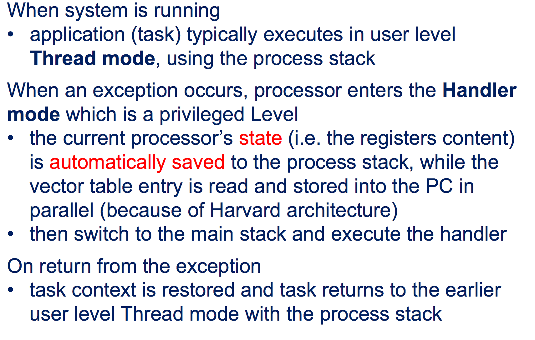
What to be stored in Process Stack?

Interrupt Handling
Various ways to handle interrupt:
non-nested interrupt handler: interrupts are handled separately and sequentially.
nested interrupt handler : allow another higher/same priority interrupt to invoke when servicing a current interrupt ( ISR re-enables interrupts before the handler has fully serviced the current interrupt)
re-entrant nested interrupt handler : allow same interrupt to invoke when servicing a current interrupt (allows multiple interrupt invocations like conventional nested version, but all are of the same origin)
Cortex M3 processor incorporates
a Nested Vector Interrupt Controller (NVIC) to implement prioritized exception and support nested interrupts.
Priority is set in the NVIC interrupt controller
The NVIC’s nested interrupt automatically allows exceptions of a higher priority task to preempt a lower priority task